Piping and Instrumentation Diagram
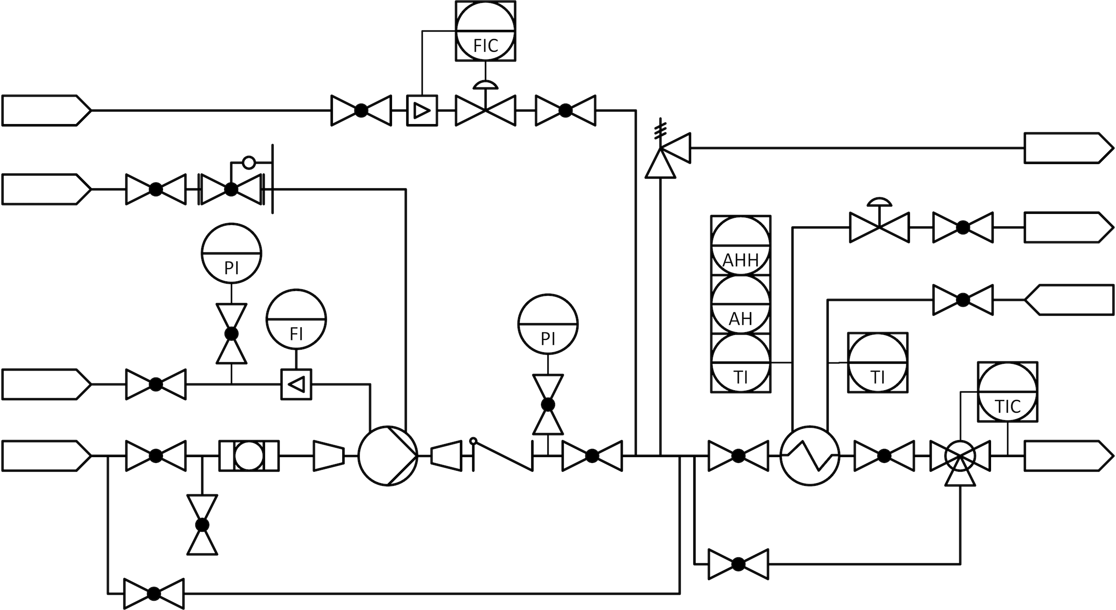
The piping and instrumentation diagram, shortened to PID, is a schematic, two‑dimensional depiction of the components, which the plant consists of. At the same time, it shows how the components are interconnected with each other and forms a visualization of the process concept. Within a plant building project, central information is shared via the PID between the groups involved in the execution process. The PID can be considered the centrepiece of the execution process, as the contained information is usually relevant for all groups and referenced by them all.
The PID is initiated at the very beginning, sees adjustment and development throughout the entire execution process up to construction and commissioning of the plant, and is potentially still referred to for operation and service works decades after the handover of the plant to the operator. It is the most important document of a plant building project, reflecting the quality of the execution process to a high degree and as such requiring special care and attention.
The PID is depicted in a rectangular format in horizontal orientation and often spans several pages. The interconnection between the single pages and the components of the plant which they show is achieved through pipelines and other components of the same type, which are represented by lines and if required can thus be routed across multiple pages. At the transition between two pages, the corresponding ends of such a line are marked by a reference, which points to the continuation of the line on the other page.
Usually, the PID is preceded by the creation of a process flow diagram.
Technical Data
Only a limited amount of technical data is given on the PID alongside the depiction of the components. Nominal diameter and nominal pressure values are considered a standard. The same applies for the set pressure of safety valves and rupture discs.
Component Identification
All the components depicted on the PID are marked by a unique identifier, usually consisting of a combination of letters and numbers. This also applies to subroutines of the process control system, which are referenced on the PID, such as control loops.