Shut‑Off Valves
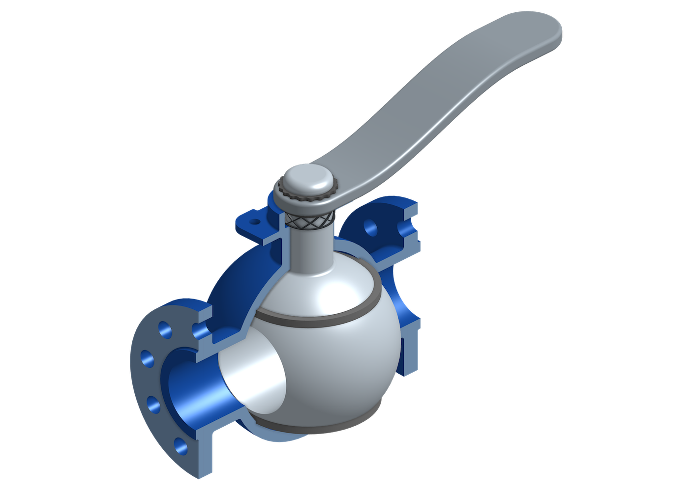
Shut-off valves are used to isolate single components or plant sections and to interrupt process flows. As separating elements they facilitate local maintenance and repair works, inspections and retrofits as the separation eliminates the need to shut down the adjacent plant sections. The interruption of a process flow by means of a shut‑off valve is either done as part of the process concept or it is a safety functionality. Shut‑off valves are available in different types such as ball valves, gate valves, or butterfly valves. Which type is suitable depends on the pressure and temperature requirements, the permitted pressure losses, as well as the quality of the process media.
Kvs‑value and free Cross‑Sectional Area
In spite of the same functionality, different shut‑off valves differ from each other, among other things in terms of the free cross‑sectional area as well as the Kvs‑value, meaning the pressure loss they cause for a given flow rate. Usually, shut‑off valves are preferred to cause as small a pressure loss as possible. Exceptions from this may be shut‑off valves which, in addition to their blocking function when closed, shall serve as a flow limiter when open. Generally, the free cross‑sectional area is preferred to be as big as possible, ideally as big as that of the connecting pipes. This is particularly valid in the case of process media containing solid particles.
Leakage
For a shut‑off valve in closed condition, leakage across the valve must be taken into account. Depending on the situation, even low leakage rates can lead to contamination or an increase of the pressure on the side with the lower pressure if that side represents a closed volume. Protection against overpressure might have to be considered, for example by means of a safety valve, if adjacent process volumes that are separated by a shut‑off valve have different design pressures. The risk of harmful effects due to leakage can be mitigated by the use of so‑called double‑block‑and‑bleed arrangements. Instead of using just one shut‑off valve, adjacent process volumes are separated by means of two shut‑off valves arranged in series. When the two valves are closed, the enclosed process volume in between them is vented by means of a third shut‑off valve connected to that volume. This way, any leakage across the two main shut‑off valves can be vented to an appropriate location in order to prevent contamination or an increase in pressure.